


Disconnector (hereinafter referred to as isolation switch) is a three-phase AC outdoor high voltage switchgear with rated frequency of 50Hz and rated voltage of 110KV, to make and break high voltage circuit with rated voltage of 110KV when having voltage and no load. The isolation switch meets the requirements of GB1985-2004 AC High Voltage Isolation Switch and Grounding Switch.
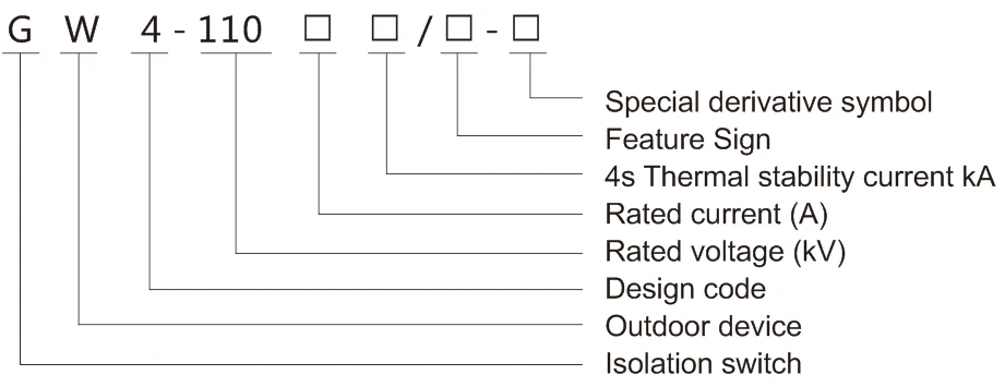
Feature sign: D - ground switch, III - ground switch type, G - improved product.
Special derivative sign: W - Stain resistant type, GY - Plateau type, H - High and cold type, TA - Dry heat type, TH - Damp-heat type.
1. Altitude: general type does not exceed 2500m, special type does not exceed 4700m.
2. Ambient temperature: the max temperature is not higher than +40°C, the min temperature is not lower than -40°C.
3. The max wind speed is 34m/s.
4. Earthquake intensity does not exceed 8 degrees.
5. Ice thickness is not more than 20mm.
6. Contamination resistant products are suitable for medium contamination areas.
7. Does not apply to the place with flammable substances, explosion hazards, chemical corrosion and severe vibration.
Main specifications and technical parameters of isolation switch
|
Item |
|
||
|
Rated voltage kV |
110 |
||
|
Maximum working voltage kV |
126 |
||
|
Rated current A |
630 |
1250 |
1600 |
|
Rated peak withstand current kA |
63 |
80 |
100 |
|
4S rated short-time withstand current kA (valid) |
25 |
31.5 |
40 |
|
Rated static tension of terminal N |
≥750 |
||
|
Rated frequency Hz |
50 |
||
|
1min Power frequency withstand voltage kV (valid) |
Ground 230 |
||
|
Fracture 265 |
|||
|
Lightning impulse withstand voltage kV (peak) |
Ground 550 |
||
|
Fracture 650 |
|||
|
Weight per pole kg |
≈240 |
Ground ≈260 |
|
|
Operating mechanism |
Isolation switch: CS14G manual mechanism or XCJ- I electric mechanism. Grounding switch: CS14G manual |
||
|
Mechanism weight kg |
CS14G manual mechanism 10 XCJ- I mechanism 50 |
||
|
Grounding form |
Ungrounded, single grounded or double groundinged |
||
|
Post insulator creepage mm |
Common type 3150/ pollution resistant 3600/3906 |
||
|
Closing synchronism |
≤10mm |
||
Main specifications and technical parameters of XCJ-I motor-drive mechanism
|
Item |
technical parameters |
||
|
Motor |
Rated voltage V |
AC/DC 220 (110) |
|
|
Rated power kW |
0.41 |
||
|
Rated speed r/min |
916 |
||
|
Starting current A |
≤5 |
||
|
Control voltage of open-close switch V |
DC220V, DC110V, AC220V |
||
|
Rated operating time s |
≤2 |
||
|
Rated output distance N.m |
550 |
||
|
Parameters of auxiliary switch |
Normally opened contact |
10 pairs |
|
|
Normally closed contact |
10 pairs |
||
1. Outdoor Disconnector | Isolation Switch
The Outdoor Disconnector is a horizontal rotating double column type, consisting of the underframe, post insulator, conductive system, grounding switch (except for grounding) , and transmission system.
2. Underframe: for a channel steel, each end of the underframe is equipped with bearing seats, and there are two tapered roller bearings in the bearing seat to ensure the flexible rotation of the lever on the bearing seat. One or both ends of the underframe are welded with the grounding switch bearing, and the grounding switch is installed. The isolating switch has three forms: no grounding, single grounding and double grounding.
3. Pillar insulators: each pole has two columns, divided into three kinds according to the use conditions: common type, anti pollution type and plateau type. The lower end of the pillar insulators is fixed on the rotating plate of the upper end of the bearing seat, and the upper end of the pillar insulators is connected with the leading electric part. Silicone rubber insulators can also be used as pillar insulators according to users' requirements.
4. Conducting system: the conductive part is fixed on the upper end of the pillar insulator. The main knife is divided into two half, the contact part is in the middle, the cylindrical contacts are embedded in the two row contact fingers when closing. The structure types of 630A, 1250A and 1600A are the same, there are only differences between conductor section and surface treatment. The outlet structure is the rolling contact or soft connection structure, choose one type according to user's order.
5. Grounding switch: the grounding switch installed in the rotating shaft of the base. The static contact is installed on the conductive rod of the leading electric system, and mechanical interlock is installed between the grounding switch and the isolation switch. It can ensure the action sequence of main open-ground close, ground open-maind close. Ground switches are divided into single ground and double grounding, can be grounded from the inside to the up, or from the outside to the up. It can be adjusted according to the needs of users.
6. Transmission system: Isolating switch is driven by the operating mechanism to drive the rotating shaft of the middle base to rotate 180°, and rotate 90° by the pillar insulator (installed on the rotating lever) on one side of the horizontal linkage, and the other pillar insulators are rotated 90° by the cross connecting rod, and the two knife is opened or closed to one side. When the ground switch operation mechanism is opened or closed, the rotation shaft of the grounding switch can be rotated at an angle to open and close by the transmission shaft and horizontal connecting rod. Because the fanning plate on the grounding switch shaft is interlocked with the arc plate fixed on the flange of the porcelain column, it can ensure the action sequence of main open-ground close, ground open-maind close.
The isolation switch is made into 1-pole form, and the three-pole linkage is formed through the phase-to-phase connection (see FIG. 1, FIG. 2) and can also be used as 1-pole.
7. Operating mechanism
The isolation switch is generally equipped with CS14G manual mechanism, and can also be equipped with XCJ-I type electric mechanism.
Details of the XCJ-I electric drive mechanism are shown in the XCJ-I type electrical machinery installation instructions.
The grounding switch is equipped with CS14G manual mechanism and accessories, single grounding for one set, double grounding for two sets.
The CS14G type manual mechanism is mainly composed of base, handle and auxiliary switch. The auxiliary switch has 8 pairs of normally open and 8 pairs of normally closed contacts for interlocking and signal display.
Refer to the following steps for installation
1. The base of 1P isolation switch is fixed on a horizontal basis, and the rotating shaft of the three-phase earthing switch is adjusted to the same horizontal axis.
2. Check the contact condition in the middle of the isolation switch. Single phase should be satisfied:
a. When the middle contact is closed, the cylindrical contact and the two rows of contact fingers should be in contact at the same time, if necessary, adjust the cross-screw (left and right bolts) to achieve;
b. The contact of the middle contact is symmetrical, and the difference between up and down is not greater than 5mm, closing to the end, the intermediate gap adjusted to 7 ~ 12mm, if necessary, in the support of the root with increasing or decreasing shims to achieve, but the thickness of each pad should not be greater than 5mm;
c. The main knife rotates 90° to opening the closing end position, the gap between the set screw and the baffle shall be adjusted to 1~3mm.
3. Install the linkage rod in the three phase of the main knife according to figure 1, and adjust length of the connecting rod to make three phase closing synchronism does not exceed 10mm, and the two sides of the three phase linkage rod and the cross connecting rod between the pillars have the left and right screws respectively, which can be adjusted directly according to the needs.
4. Install the connecting rod between three phases of the ground switch according to figure 1, tighten the screws and adjust the operation lever, the mechanical interlocking lever, the torsion spring and the fixing ring. Tighten the bolts after torsion spring adjusts to the grounding switch is in the horizontal position when opening.
5. Install the CS14G or XCJ-I motor-drive mechanism on the bracket convenient for manual operation, taking the drive shaft on the isolation switch chassis as the center . The vertical axis method is used to ensure that the spindle of the mechanism coincides with the rotation axis, and fasten mounting bolts on the mechanism.
6. The mechanism and the isolation switch are in the state of opening or closing at the same time. The connection head and linkage rod are used to connect the isolation switch shaft and the mechanism spindle, and the following requirements are achieved.
a. Operate 3~5 times and check the isolation switch to meet the requirements, the opening angle of the isolation switch is 90°, and there should be 1 to 3mm gap between the positioning screw and the baffle;
b. Adjust the static contact of the grounding switch and tighten the bolt, so that the earthing contact can be inserted correctly when the grounding switch is closed.
c. Adjust the balance spring on the rotating shaft when opening, to make ground switch keep at horizontal position.
d. Check the mechanical interlock between the isolation switch and the ground switch to ensure that the grounding switch can not be closed when the isolation switch is closed. The isolation switch can not be closed when the grounding switch is closed. When all the operation is correct, we should drill φ8 holes and 8 x 60 elastic cylindrical pin at the connecting place of the three phase grounding switch shaft, and drill φ12 holes with depth ≥5mm at the location rod, drive lever, linkage lever and rotating shaft, tighten the bolts in each place, and clean the ground soft connection to keep contact with the metal gloss surface.
7. The installation adjustment is only allowed to use manual operation. After the adjustment is completed, if the manual operation is used to confirm the correctness, the electric operation (when equipped with the electric mechanism) can be used.
8. Check after installation and commissioning
9. The isolation switch and the grounding switch are manually operated for 3 to 5 times respectively, and the operation is stable, the contact is good, and the position of the closing and closing is correct.
10. Power distribution mechanism is operated 5 times under the rated operating voltage of the motor, and operates 3~5 times respectively in 85% motor and110% rated operating voltage. The opening-closinge should be correct and the opening-closing time is not more than 4s.
11. The contacts are in good contact with the contacts after the isolating switch is closed. The measured data of the main loop resistance (on both sides of the outgoing end) does not exceed that shown in Table 4.
12. The synchronism of the three phase closing is not more than 10mm.
13. Check whether all transmission and rotation parts should be lubricated, whether all axle pin bolts are fastened and reliable.
14. Check whether the isolation switch and the ground switch are interlocked reliably.
This switch must be operated after the line load is cut off.
The switch should be regularly overhauled (about 1~2 years). If there is a serious short-circuit fault, it should be repaired immediately after the failure.
Remove the dirt from the surface of conductive parts and pillar insulators, the connection plane and the middle contact between connection terminal and the busbar, button contact surface, and then apply the industrial vaseline oil.
Careful inspection of post insulators should be made without any bruises and cracks, and should be replaced if found.
The transmission and rotation parts should be lubricated.
Check all fasteners such as whether taper pins and bolts are loose.
Check the manual mechanism, whether the auxiliary switch can switch normally when the handle is rotated 180°.
The isolation switch and grounding switch are generally packed in three pole common box, and can also be packed in bulk. In bulk packing, it is divided into base box, pillar insulator box and conductive system (including accessories) box, and one box per group at single pole order.
The reverse sign should not be allowed outside the packing box when the product is transported.
After receiving the product, please check it in time. If there are any problems, you should contact the manufacturer
Address
No.2567 Liuqing South Road, Liushi, Yueqing, Wenzhou, Zhejiang, China
Tel