


GN19-12 Indoor High Voltage Isolation Switch (also known as the indoor high voltage AC drop-out fuse) is the indoor device with rated voltage 12kV, three phase AC 60Hz, used to break and make circuit under no-load but with voltage.
The upper limit of ambient temperature is +40℃, the lower limit is -10℃, Note: Storage and transportation at -25℃.
Altitude does not exceed 1000m
Relative humidity: daily average ≤95%, monthly average ≤90%.
Steam pressure: The daily mean value is not greater than 2.2x10⁻³Mpa, and the monthly mean value is not greater than 1.8*10-3Mpa
Ambient air should not be polluted by corrosive or flammable gases or steam.
Indoor High Voltage Isolation Switch Applicable occasions should free from severe vibration.
Note: if it is not in conformity with the above conditions, please consult with the manufacturer.
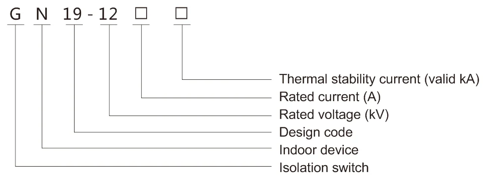
|
Model |
Rated voltage (kV) |
Rated current (A) |
4S Thermal current (kA) |
Dynamic current (kA) |
|
GN19-12/400-12.5 |
12 |
400 |
12.5 |
31.5 |
|
GN19-12C/400-12.5 |
400 |
12.5 |
31.5 |
|
|
GN19-12/630-20 |
630 |
20 |
50 |
|
|
GN19-12C/630-20 |
630 |
20 |
50 |
|
|
GN19-12/1000-31.5 |
1000 |
31.5 |
80 |
|
|
GN19-12C/1000-31.5 |
1000 |
31.5 |
80 |
|
|
GN19-12/1260-40 |
1250 |
40 |
100 |
|
|
GN19-12C/1260-40 |
1250 |
40 |
100 |
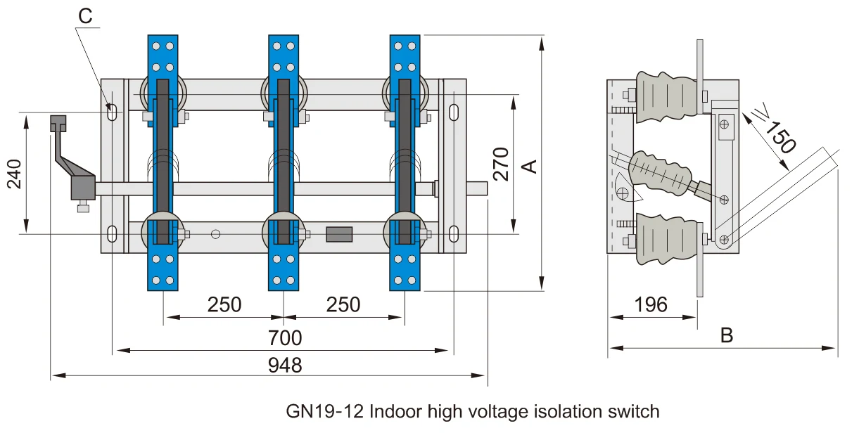
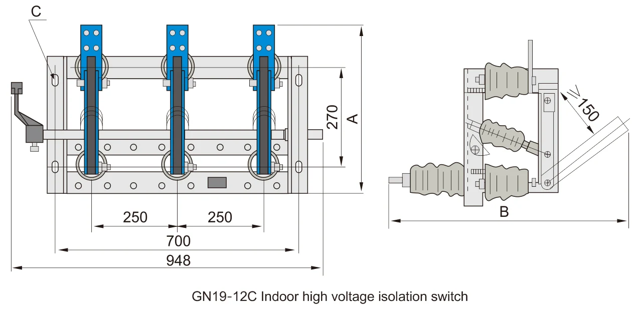
The conductive parts of each phase of GN19-12 Indoor High Voltage Isolation Switch are fixed on the base by two post insulators (For GN19-12C is a post insulator and a porcelain casing insulator). Three phase parallel installation, the conductive part is composed of the contact knife, static contact and contact seat (or conducting rod). Each contact knife is connected with pull rod insulator, and the pull rod insulator is connected with the spindle mounted on the base. The spindle is connected by the handle with the connecting rod (the user self) and the CS6-1 type to the moving mechanism. The contact knife is composed of two slot shaped copper plates. It not only increases the heat dissipation area of the touch knife, but also improves the mechanical strength of the cutter, and improves the dynamic stability of the switch. One end of the contact knife is mounted on the contact seat (or the conductive rod) through bolts. The other end is connected with the static contact system, and the contact pressure of the contact knife is maintained by the springs at both ends. GN19-12/1000 and 1250 are installed with magnetically locked plates, and the purpose of adding a magnetic locking plate is to enhance the attractiveness between the two grooves when a large short circuit current passes through. That is to say, the contact pressure at the contact point is increased, thus improving the dynamic thermal stability of the switch. GN19-10/400A and GN19-12/630 isolator has low through current, so there is no need to add a magnetic locking plate.
Base assembly: consists of base, main shaft, limiter, stopper ring and other components. The limiter is mainly used to ensure that the conductive contact knife reaches the desired terminal position when closing and opening.a
Pre-installation preparation
1. Open the packing box and check whether the product spare parts and the accompanying technical documents are complete according to the packing list. Check whether the product is damaged during transportation and storage.
2. Eliminate dust and dirt inside the product. Wipe the porcelain insulator and the grounding surface of the chassis carefully.
3. Apply industrial Vaseline to all mechanical friction parts.
4. The Indoor High Voltage Isolation Switch and manual mechanism can be installed vertically or horizontally in the opening cabinet or on the wall. Refer to several typical installation illustrations 7, 8, 9, 10.
5. The installation height of the isolating switch is generally 2.6~6 meters (from switch shaft to the ground). The distance from the handle fulcrum to the ground is 1~1.3 meters.
The rotation angle of the manual mechanism after installation shall be matched with the rotation angle of the spindle when the GN19-12 isolation switch is on / off. The adjustment process is carried out in the following ways:
5a. The connecting rod connecting the Indoor High Voltage Isolation Switch and the manual mechanism is composed of the connecting piece and 3/4 gas pipe (user-supplied). Both ends of the rod are connected with the connecting piece, One end of the connecting piece can adjust the length of the connecting rod through bolts, and the length of the pipe is determined by the position of the manual mechanism and the isolation switch. If the arm of the manual mechanism is not in the same plane as the arm on the main shaft of the isolation switch, the connecting rod can be bent so that the switch and the mechanism can be connected correctly, and the length of the bolt can also be adjusted.
5b. Determine the initial angle of the main shaft of the Indoor High Voltage Isolation Switch according to the adjustment requirements. Then drill into the positioning pin and fix the crank arm.
5c. Position from opening to closing of the manual mechanism is compatible with the position of starting and ending position of the Indoor High Voltage Isolation Switch stop, which can be adjusted by different connection holes in the sector plate in the manual mechanism.
6. 3~6 operations after the isolation switch is adjusted, it is not allowed to get stuck or other abnormal phenomena that impede its operation.
7. When the handle of the manual mechanism is upward during operation, the Indoor High Voltage Isolation Switch should be in the closing position and should be in the opening position when the handl is downward. In the opening-closing position, the positioning pin of the mechanism should lock the handle reliably to avoid misoperation.
8. After the Indoor High Voltage Isolation Switch is off, the shortest distance between the same pole break should not be less than 150mm.
9. When the auxiliary switch action does not meet the requirements, the position of the hole in the linkage arm can be adjusted so that the contact of the auxiliary switch can be accurately closed. Even if the manual mechanism reaches the opening position, the normal opening contact of auxiliary switch should be in the closing position.
10. The auxiliary switch indicates that the opening-closing signal of the Indoor High Voltage Isolation Switch shall be given after the knife passes 75% of its full stroke. The signal indicating the closing of the isolating switch should be given after the isolator's knife contact with the contact.
11. Ground contact must be good and the ground loop resistance must not exceed 3 ohms.
12. The contact between the terminal and the busbar must be good and reliable. Avoid the Indoor High Voltage Isolation Switch being subjected to mechanical forces from the bus.
13. The insertion depth of the screws fixing the switch to the wall shall not be less than the following: Brick wall: 90mm, Cement: 76mm
14. The contact between the contact blade and the static contact should be good. The positive pressure of the pressure spring on the contact surface should reach the following values:
|
Rated current (A) |
400 |
630 |
1000 |
1250 |
|
Positive pressure (N) |
392±39 |
431±39 |
441±44 |
441±44 |
Indoor High Voltage Isolation Switch must be serviced when the circuit and power supply are cut off, ie they are not powered.
After the Indoor High Voltage Isolation Switch is opened, the shaft pin attached to the mechanism must be inserted into the hole on the frame to lock the pin pin to ensure absolute safety.
During the inspection, check in detail whether the insulation moleculesis damaged and check whether the contact is good.
Repair the contacts burned, remove dirt, especially conductive contact parts and insulator surfaces. After inspection, apply industrial Vaseline on contact surfaces.
Check whether the fastening is firm and check whether the grounding is good. (The ground screw is not allowed to loosen and there is rust at the contact.)
It is necessary to replace the contact, the contact knife with serious damage and the residual deformation of the pressure spring before they can be used.
After completion of all maintenance and installation, several opening and closing tests shall be carried out. If it is not proper, it shall be readjusted until it is normal before it can be put into operation.
Rotate the friction part in the mechanism and coat it with industrial petrolatum.
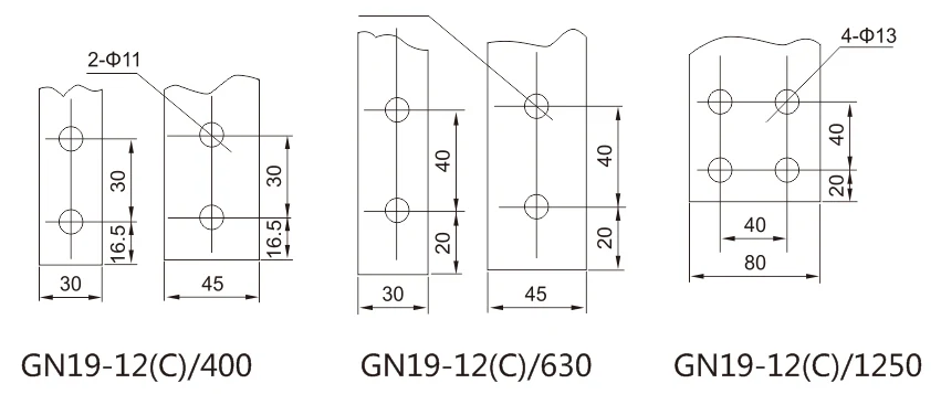
GN19-12(c)Indoor high voltage Indoor High Voltage Isolation Switch Unit: mm
|
Model |
12/400 |
12/630 |
12/1250 |
12C/400 |
12C/630 |
12C/1250 |
|
A |
450 |
490 |
510 |
420 |
460 |
505 |
|
B |
436 |
436 |
530 |
625 |
625 |
745 |
|
C |
4-14*24 |
4-14*24 |
4-18*28 |
4-14*24 |
4-14*24 |
4-18*28 |
Address
No.2567 Liuqing South Road, Liushi, Yueqing, Wenzhou, Zhejiang, China
Tel