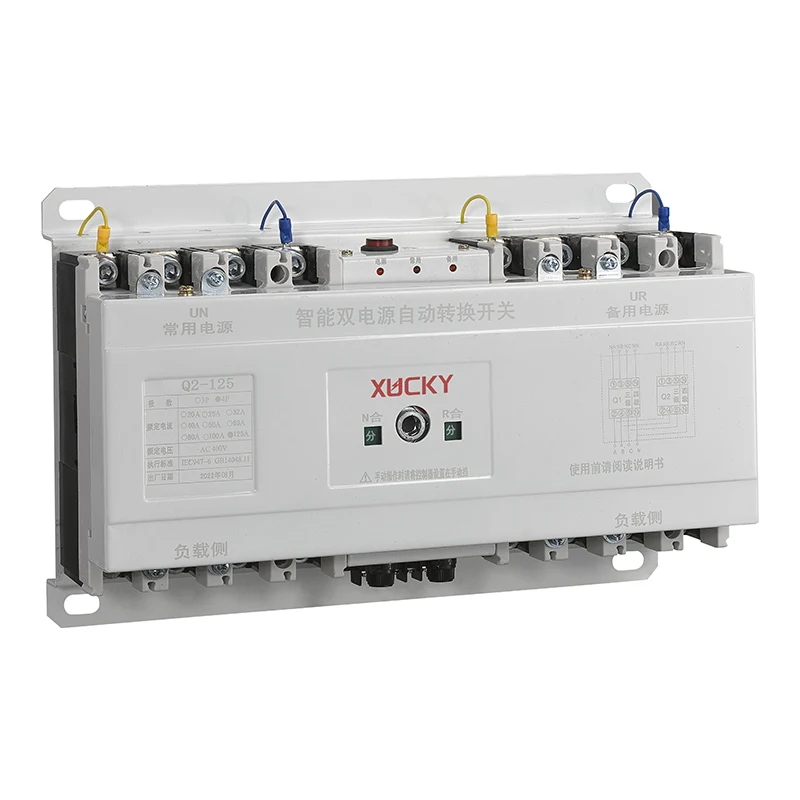
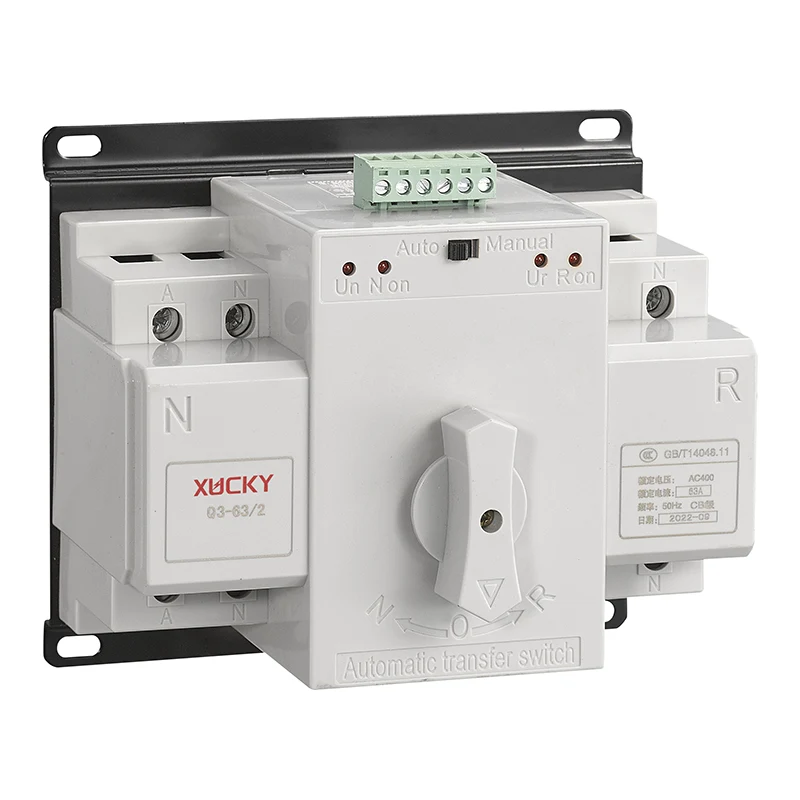
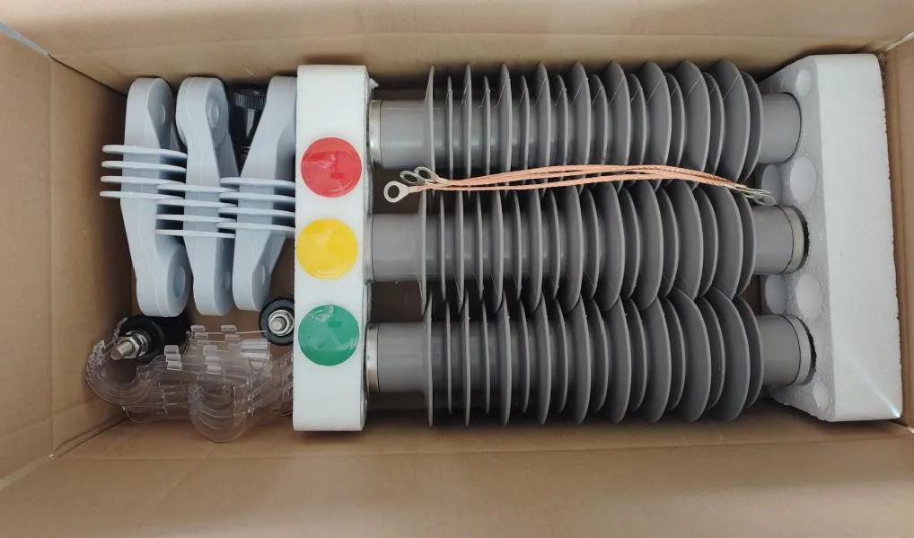
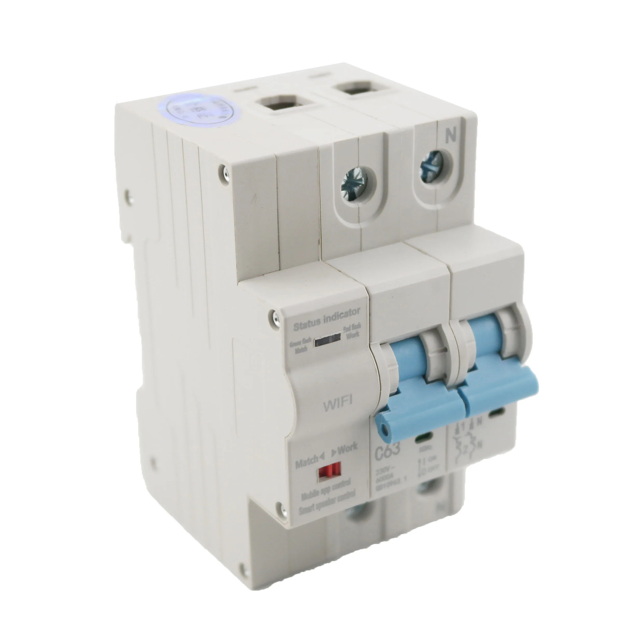
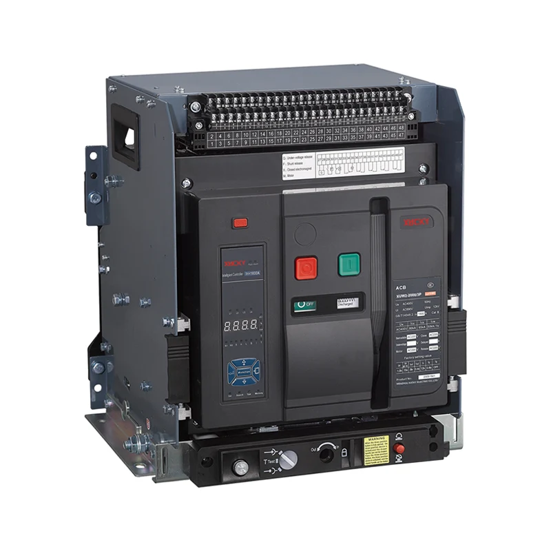
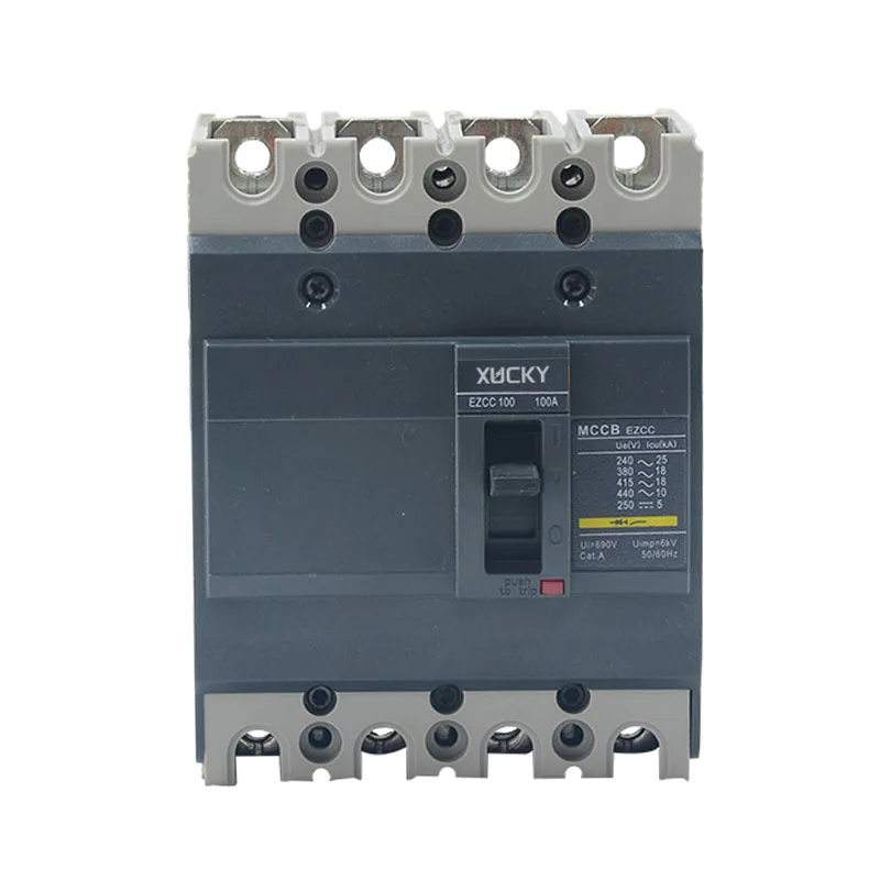
Q2 Automatic Transfer Switch (hereinafter referred to as ATS switch, also known as home transfer switch) for dual power supply system of AC 50Hz, rated voltage of 380V, rated current of 63A~630A, use automatic or manual operation modes to switch between the common power supply and standby power supply. The home transfer switch is mainly used for hospitals, shops, banks, chemical industry, metallurgy, high-rise buildings, military facilities and other important occasions.
This home transfer switch meets GB / T14048.11-2005 "low-voltage switchgear and controlgear - automatic transfer switching equipment" standard. This product electrical level is CB-class.
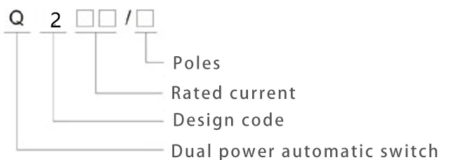
Models and Specifications
Normal working conditions
● Ambient air temperature: -5℃~+40℃, and average temperature in 24h is less than +35℃;
● Atmospheric relative humidity is not more than 50% at ambient air temperature of +40℃, there is higher relative humidity in the low temperature. The average maximum relative humidity wettest month of the wettest month is 90%, while the average minimum temperature of this month is +25℃. Taking into account the condensation on the surface of the product due to temperature changes;
● Altitude of installation site is not more than 2000m;
● Installation category: IV;
● This ATS switch should be installed in the place without severe vibration, shock and corrosion;
● Use category: A;
● When the above conditions can not be met, should be resolved by user and manufacturer through consultation.
Basic structure
Q2 Automatic Transfer Switch is mainly composed of power conversion circuit breaker, switch work has three status positions for the user to choose: common power (N) closing, double-opening, standby power (R) closing, the home transfer switch has small size, light weight , stable operation, easy to use and so on.
Installation and use
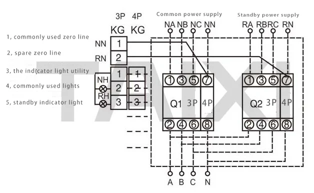
When wiring, the common power supply N should be connected to the common power supply circuit breaker QN, and the standby power supply R should be connected to the standby power supply circuit breaker QR. When QN and QR are four-wire circuit breakers, the connection mode is according to the wiring diagram, the 1, 3, 5 of QN and QR are three-phase (A, B, C) inlet terminals, 7 is the zero line (N) inlet terminal, 8 is the zero line outlet terminal. If the circuit breaker is a three-pole circuit breaker, it is necessary that the zero line NN of the common power supply (N) and the zero line NR of the standby power supply (R) must be connected to the three-pole special zero line terminal KG. Specific operation see wiring diagram. The power supply Dual power switch automatic controller take inlet line A-phase and zero line N of circuit breaker QN and QR, if use the three-pole circuit breaker, must be connected to the zero line NN and NR, the three-pole dedicated zero terminal is between two circuit breakers, in the installation and wiring of automatic power switch, do not make the local controller line connected to inlet terminal of the circuit breaker forgotten, break or have short circuit.
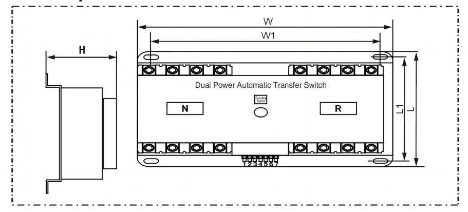
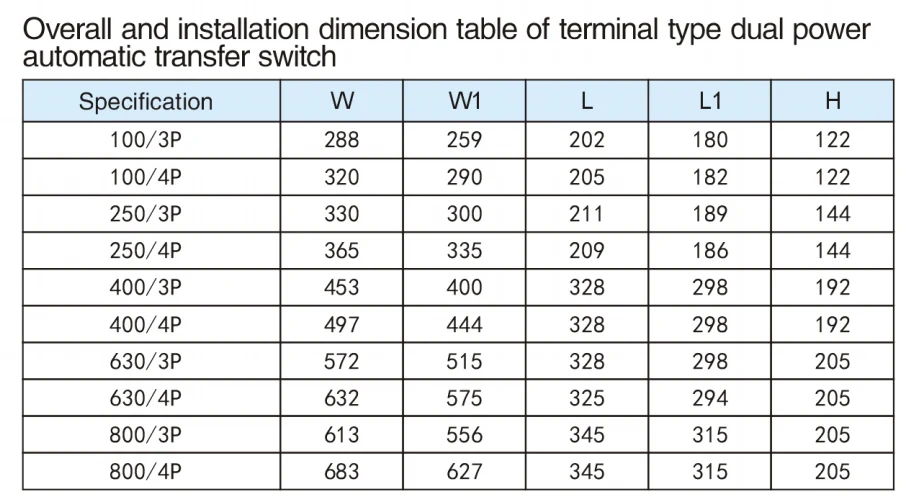
Installation dimensions
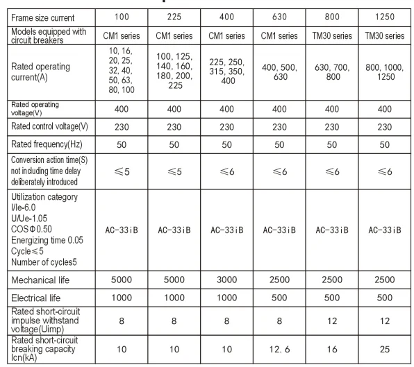
Technical parameter
Use operation
Whether the common power supply and standby power supply voltage, both can use manual operation. When the manual operation, the manual-automatic button should be placed in the manual operation position, when pushing handle clockwise to the terminal, the standby power supply circuit breaker QR is opening, the common power circuit breaker QN is closing; when pushing handle counterclockwise to the terminal, the standby power supply circuit breaker QR is closing, common power supply circuit breaker QN is opening.
On the panel, the power indicator (red), if the light is not on, indicating that the automatic control box power supply has failure, can not operate the ATS switch. After repaired to normal, manual-automatic button is on the automatic position, if the common power supply is normal, the switch will automatically input common power supply circuit breaker QN in closing state, N indicator (yellow) is on on the panel; if the common power supply is not normal, then ATS switch will automatically switch to the standby power supply QR for power supply, standby power supply R indicator light (green) is on.
Note: The actual size shall prevail, the above data is for reference only.
Hot Tags: Q2 Automatic Transfer Switch, China, Manufacturer, Supplier, Factory
We use cookies to offer you a better browsing experience, analyze site traffic and personalize content. By using this site, you agree to our use of cookies.
Privacy Policy