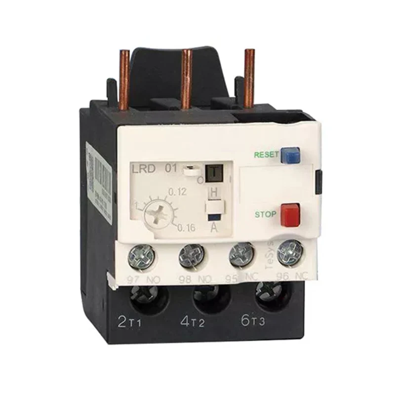
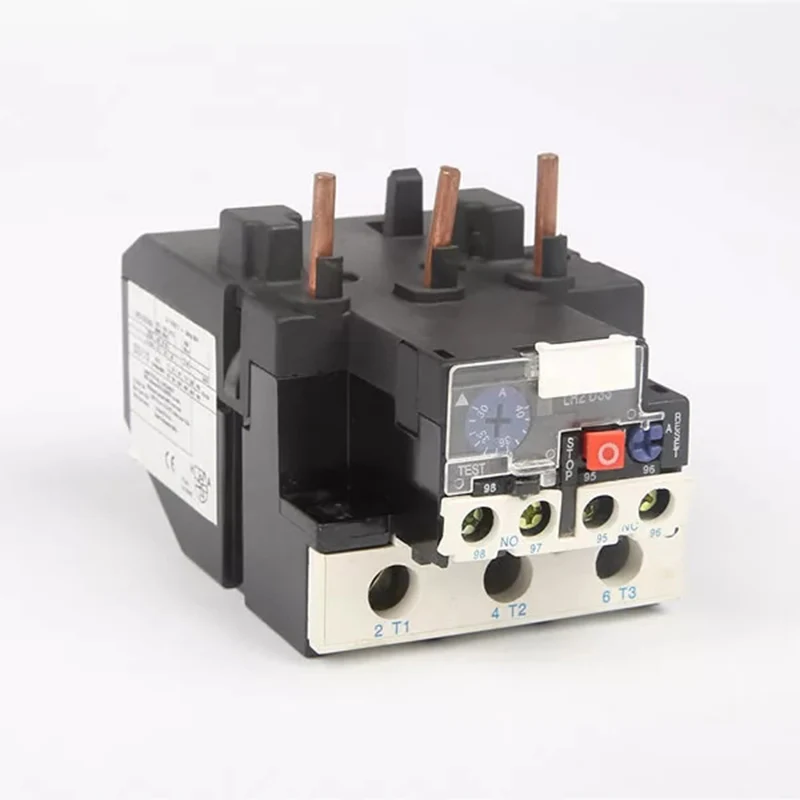
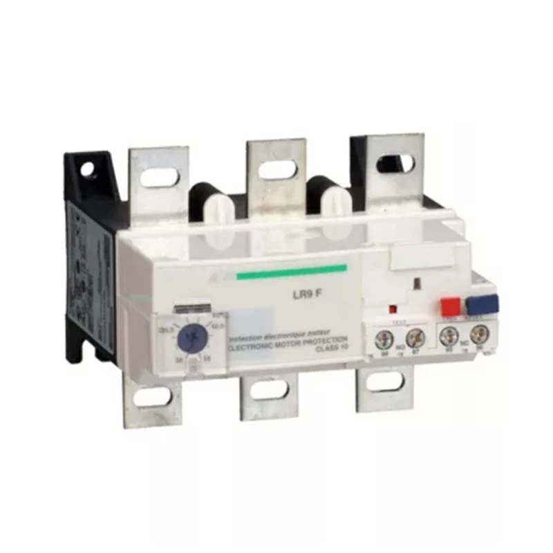
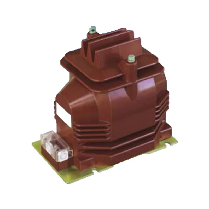
JR20 Thermal Overload Relays are suitable for circuits with AC 50Hz, voltages up to 660V, and currents up to 630A, to protect against overload, phase failure and three phase unbalance of AC motor. With phase-failure protection, temperature compensation, manual or auto reset, action tripping flexibility check, action tripping indication, disconnection check button and other functions. Products meet the GB14048.4.
Ambient temperature: The average value does not exceed +35°C in 24 hours.
Altitude: no more than 2000m.
Atmospheric conditions: The relative humidity does not exceed 50% at +40°C, and higher relative humidity may be allowed at lower temperatures. For example, 90% at 20°C, special measures should be taken for the occasional condensation due to temperature changes.
Pollution level: 3 levels.
Installation category: Class III.
Installation conditions: The inclination of the installation face and the vertical is not more than ±5°.
In addition to mounting screws, the relay can also use 35mm standard rail.
Shock vibration: The relay should be installed and used in places where there is no significant shaking, shock and vibration.
Transportation, Storage: The relay should not be subject to severe impact and vibration during transportation, and it must not be affected by rain or snow in transportation and storage. Relays are suitable for transport and storage at -25°C ~ +55°C, and at +70°C for short periods (in 24h).
Internal structure: Insert combination or independent structure; three-dimensional structure, pull spring blade jump action mechanism; with phase failure and temperature compensation structure.
Installation operation: with action tripping flexibility inspection, action tripping indication and disconnection inspection and other functions; optional manual reset and automatic reset; normally closed and normally open auxiliary contacts insulated and separated
Model |
Rated insulation voltage Ui (V) |
Thermoelement |
Rated current range (A) |
Corresponding AC contactor |
JR20-10 |
660 |
1R |
0.1~0.13~0.15 |
CJ20-10 |
2R |
0.15~0.19~0.23 |
|||
3R |
0.23~0.29~0.35 |
|||
4R |
0.35~0.44~0.53 |
|||
5R |
0.53~0.67~0.8 |
|||
6R |
0.8~1~1.2 |
|||
7R |
1.2~1.5~1.8 |
|||
8R |
1.8~2.2~2.6 |
|||
9R |
2.6~3.2~3.8 |
|||
10R |
3.2~4~4.8 |
|||
11R |
4~5~6 |
|||
12R |
5~6~7 |
|||
13R |
6~7.2~8.4 |
|||
14R |
7~8.6~10 |
|||
15R |
8.6~10~11.6 |
|||
JR20-16 |
1S |
3.6~4.5~5.4 |
CJ20-16 |
|
2S |
5.4~6.7~8 |
|||
3S |
8~10~12 |
|||
4S |
10~12~14 |
|||
5S |
12~14~16 |
|||
6S |
14~16~18 |
|||
JR20-25 |
1T |
7.8~9.7~11.6 |
CJ20-25 |
|
2T |
11.6~14.3~17 |
|||
3T |
17~21~25 |
|||
4T |
21~25~29 |
|||
JR20-63 |
1U |
16~20~24 |
CJ20-40 |
|
2U |
24~30~36 |
|||
3U |
32~40~47 |
|||
4U |
40~47~55 |
|||
5U |
47~55~62 |
|||
6U |
55~63~71 |
|||
JR20-160 |
1W |
33~40~47 |
CJ20-100 |
|
2W |
47~55~63 |
|||
3W |
63~74~84 |
|||
4W |
74~86~98 |
|||
5W |
85~100~115 |
|||
6W |
100~115~130 |
|||
7W |
115~132~150 |
|||
8W |
130~150~170 |
|||
9W |
144~160~176 |
|||
JR20-250 |
1X |
130~150~170 |
CJ20-250 |
|
2X |
167~200~250 |
|||
JR20-400 |
1Y |
200~250~300 |
CJ20-400 |
|
2Y |
267~335~400 |
|||
JR20-630 |
1Z |
320~400~480 |
CJ20-630 |
|
2Z |
420~525~630 |
Note: The 10R and below specification in JR20-10 does not include a phase failure protection device.
Utilization Category |
Rated frequency |
Rated insulation voltage (Ui) |
Rated operational voltage (Ue) |
Rated operational current (Ie) |
Conventional thermal current |
Auxiliary contact |
AC-15 |
50Hz |
380V |
127V |
2.83A |
6A |
NC 95-96 |
220V |
1.64A |
|
||||
380V |
0.95A |
|
||||
220V |
0.82A |
6A |
NO 97-98 |
|||
380V |
0.47A |
|
No. |
Setting current multiples |
Action time |
Initial condition |
||
Operation characteristics when negative each phase is balanced |
|||||
1 |
1.05 |
No action in 2h |
Cold |
||
2 |
1.2 |
Action in 2h |
Thermal (after No. 1 test) |
||
3 |
1.5 |
<2min |
<4min |
Thermal (after No. 1 test) |
|
4 |
7.2 |
2s<Tp≤10s |
4s<Tp≤10s |
Cold |
|
5 |
1.0 |
No action in 2h |
Cold |
||
6 |
1.2 |
Action in 2h |
Thermal (after No. 5 test) |
||
7 |
1.05 |
No action in 2h |
Cold |
||
8 |
1.3 |
Action in 2h |
Thermal (after No. 7 test) |
||
Operation characteristics when negative each phase is unbalanced |
|||||
|
Any two phase |
Third phase |
|
||
1 |
1.10 |
0.9 |
No action in 2h |
Cold |
|
2 |
1.15 |
0 |
Action in 2h |
Thermal (after No. 1 test) |
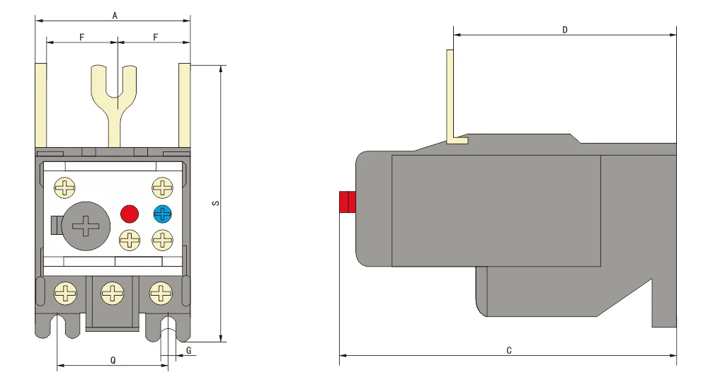
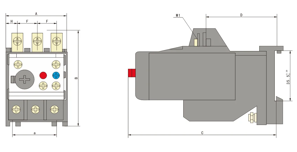
1. Outline and lnstallation Dimension of JR20-10Z/JR20-16Z/JR20-25Z/JR20-63Z/JR20-160Z
2. Outline and lnstallation Dimension of JR20-10L/JR20-16L/JR20-25L/JR20-63L/JR20-160L
3. Outline and installation dimension of JR20-10GL/JR20-16GL/JR20-25GL/JR20-63GL/JR20-160GL
Thermal Relay |
A |
B |
C |
D |
E |
F |
G |
H |
K |
a |
M1 |
M2 |
φ |
|
Model |
Feature |
|||||||||||||
JR20-10 |
Z |
44 |
77.5 |
101 |
57.8 |
|
10 |
4.5 |
13.9 |
|
32 |
|
|
|
L |
44 |
70 |
101 |
46 |
|
14 |
4.5 |
8.9 |
|
32 |
M5 |
|
|
|
G |
44 |
70 |
112 |
53 |
|
14 |
|
8.9 |
|
|
M5 |
|
|
|
JR20-16 |
Z |
44 |
78 |
101 |
71 |
|
14 |
4.5 |
12.9 |
|
32 |
|
|
|
L |
44 |
70 |
101 |
46 |
|
14 |
4.5 |
8.9 |
|
32 |
M5 |
|
|
|
G |
44 |
70 |
112 |
53 |
|
14 |
|
8.9 |
5.2 |
|
M5 |
|
|
|
JR20-25 |
Z |
47.5 |
82.5 |
117 |
66 |
|
20.5 |
4.5 |
|
|
32 |
|
|
|
L |
44 |
70 |
117 |
46 |
|
14 |
|
8.9 |
5.5 |
32 |
M5 |
|
|
|
G |
44 |
70 |
117 |
53 |
|
14 |
5.5 |
8.9 |
6.5 |
|
M5 |
|
|
|
JR20-63 |
Z |
64 |
90 |
117 |
82 |
|
20 |
5.5 |
|
|
46 |
|
|
|
70 |
90 |
117 |
92 |
|
28 |
5.5 |
|
|
46 |
|
|
|
||
L |
65 |
80 |
117 |
62 |
|
23 |
5.5 |
|
|
46 |
M6 |
|
|
|
65 |
80 |
117 |
62 |
|
23 |
|
|
|
46 |
M6 |
|
|
||
G |
|
|
|
|
|
|
|
|
|
|
|
|
|
|
|
|
|
|
|
|
|
|
|
|
|
|
7 |
||
JR20-160 |
Z |
104 |
100 |
152 |
87.5 |
87.5 |
29 |
|
|
|
37 |
M6 |
M8 |
7 |
104 |
100 |
152 |
87.5 |
87.5 |
45 |
|
|
|
37 |
M6 |
M8 |
|
||
L |
|
|
|
|
|
|
|
|
|
|
|
|
|
|
|
|
|
|
|
|
|
|
|
|
|
|
|
Address
No.2567 Liuqing South Road, Liushi, Yueqing, Wenzhou, Zhejiang, China
Tel